Gogi Kvaratskhelia and ,,Lockheed Martin" Path from light beam diffraction to the pinnacle of aerodynamics
21-04-2023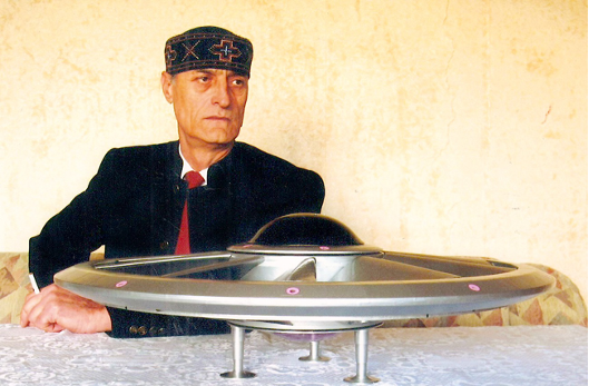
KA-100 F-35B
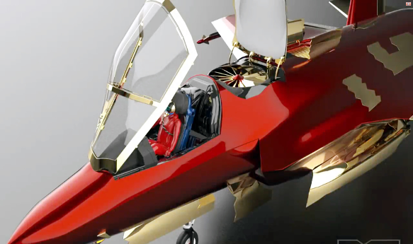
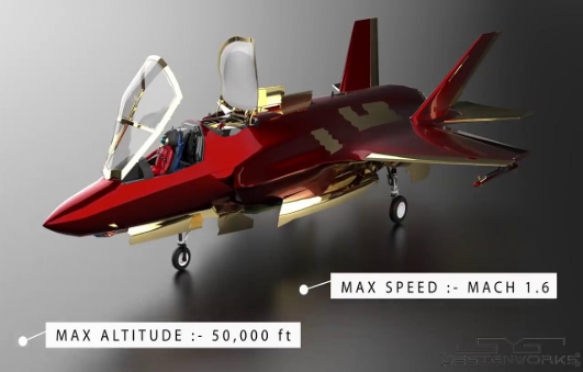
The construction of the lifting screw used in aircraft of Airline company "Lockheed Martin" Model F-35B , its operating principle and gains are noteworthy because the supporting evidences and reasons were presented much earlier, in the patent GE P 2000 1979 B of Colonel Gogi Kvaratskhelia, Head of the University Scientific Research Center for High Precision Mechatronic Technologies of Georgian Technical University, honorary doctor of Stu, which was published as of 05.12.1999.
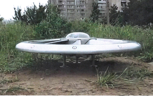
Mr. Gogi Kvaratskhelia's patent related to the flying machine and the method of its movement, based on which is it obviously visible the principle used in the F-35B fighter designed and manufactured by ‘’Lockheed Martin’’. It may be argued, that the preceding technical solution evaluated by G. Kvaratskhelia represented the pinnacle of engineering thinking at that time, and as practice has shown, it remains relevant even a dozen years later.
(I don't blame anyone and I don't make any claims. On the contrary, I am glad that the construction principle of my non-traditional disc-shaped flying machine was used by the engineers of this huge airline company "Lockheed Martin". Therefore, despite my thorny life path, I still consider myself as fortunate man because God has enabled me to realize my earliest ideas in many areas while I'm alive, and it doesn't matter where and in which country.
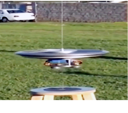
Here I would like to take this opportunity to thank the only sponsor during my many years of scientific work, the owners of "Megvineoba Khareba" ("Winery Khareba"), the Kharebava brothers, who correctly evaluated my project and provided me with financial assistance. With their help, in 2014-2016, for two years, I conducted about 50 bench tests and calculated almost all the parameters of the working model of the construction. Once again, I would like to thank the Kharebava brothers and Mr. Davit Gulua, for the help they selflessly gave me.)
During the similarity of the mechanism or principle of the lifting force, if we make a comparative analysis of the object protected by the patent of G. Kvaratskhelia and the constructions of the F-35B model, we can go over some of the benefits of the object produced by G.Kvaratskhelia and some of the disadvantages of the F-35B model construction. For example: the main, double lifting force implemented in Kvaratskhelia’s project.

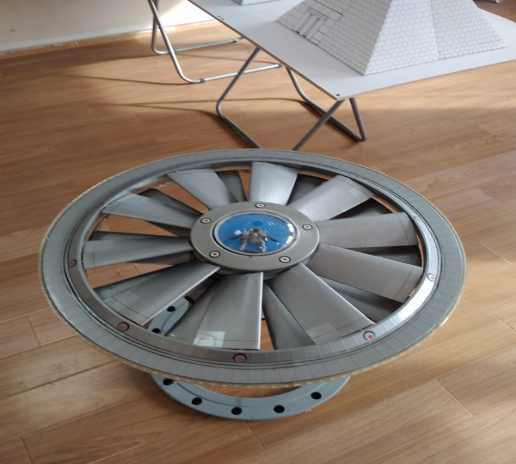
a) In the flying machine created by G. Kvaratskheliya , wingtips of the upper and lower propellers are belted, while in F-35B each propeller wing tip of the lift co-axial scheme is free. It is evident that a distinct structural element used to bind the free ends, Just like in Mr. G. Kvaratskhelia’s flying machine, increases the stability of the screws.
b) In the flying machine created by G. Kvaratskheliya, the upper and lower propeller blades are inclined towards each other through the ends, and in the F-35B model, the upper and lower propeller blades are located in parallel planes. This arrangement of wings in parallel planes leads to a relatively equal distribution of loads along each wing due to the equalization of air pressure between the wings, however, part of the air flows will move towards the ends of the wings due to the twisting of the flow in the already mentioned different directions, which can be the basis for the generation of vibrations. In addition, for the construction of such a structure a lot of effort is put in pre-selection of the optimal distance between the set screws, because a relatively large distance will worsen their performance, and their relatively close arrangement may cause undesirable convergence of the wing tips.
In G. Kvaratskhelia’s flying machine, such possible problems were eliminated precisely by tilting the ends of the wings of the upper and lower propellers towards each other, that is, by placing an imaginary conical surface along the lateral eight, so that a conical space is formed between the wings, by establishing such an area, the air pressure rises from the axis to the wings' periphery, which, as already mentioned, is bound by the salt. It is evident that the probability of occurrence of vibrations in such a construction is quite low, and even if it does, it won't be significant enough to affect general characteristics. A low-pressure area near the axis of rotation will relieve the kinematic chain connecting the drive from the transmission of additional stresses.
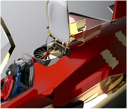
c) In the flying machine of G. Kvaratskhelia operating on the principle of the co-axial aerial scheme And the F-35B model in the lifting air propeller uses the principle of deflection with respect to the axis of rotation of the propeller. Despite such similarities, Kvaratskhelia’s device additionally uses the principle of turning the wing at an angle around its own axis. Such an additional function gives it an advantage not only in terms of aerodynamics and air flow management, but generally affects the structure as a whole due to the configuration of the wing arrangement on each propeller. In the Kvaratskheliya flying machine, the wings on the propellers are arranged in such a way that the wings of their placement angle of zero or close to zero have the opportunity to be placed on top of each other. If the F-35B model had lifting propeller wings formed in such a constructional form, then, when arranging it accordingly, there might be no need to include at least the upper door of the plot in the construction.
d) In G. Kvaratskhelia’s flying machinea separate independent actuator is used for each coaxial propeller, while the F-35B model has a single actuator in the lifting propeller and rotation of the propellers in different directions is provided by a conical With gear reducer. The presence of independent drives for air screws in the Kvaratskhelia’s flying machine ensures their rotation at different angular speeds, which one the lifting air screw of the mentioned model lacks, When using the structure formed in this way in the F-35B model, it provided, for example, a high degree of control of air flows and at the same time possibly eliminating the need for moving-wing louvres in the lower part of the air-lifting propeller plot structure.
In the construction of G. Kvaratskhelia’s flying machine, other technical solutions are also provided, which generally give the flying machine other positive effects, although only those performance forms and principles were discussed here, which are common to the construction of one of the main nodes of the F-35B model and its mechanism of action, which were developed much earlier, at the end of the 20th century, by Mr. Kvaratskhelia. Here, it should be stated that the construction principles of the time in aerodynamics and hydrodynamics, developed by Kvaratskhelia, match one to one with some of today's new classical technologies. (flying amphibian and diving boat), sketches and photo-video materials of which are stored in Mr. Gogi Kvaratskhelia's family archive.
The employees of the Department of Engineering Physics of Georgian Technical University highly positively evaluate Mr. Gogi Kvaratskhelia's findings in the engineering field, his eagerness - to create much needed engineering equipment for the country and they are ready to offer him their expertise and experience and to assist him in any way in his patriotic, honorable task.


